Table des matières:
- Fournitures
- Étape 1: Branchez le circuit
- Étape 2: Code pour la configuration des épingles
- Étape 3: Code pour la détection par joystick
- Étape 4: Code de routine de la boucle principale
- Étape 5: Prêt à essayer
- Étape 6: Implémentation Arduino Nano pour le prototype
- Étape 7: Prototype Whack-a-MoLED emballé final pour présenter votre bien-aimé
- Auteur John Day [email protected].
- Public 2024-01-30 09:05.
- Dernière modifié 2025-01-23 14:45.
Projets Tinkercad »
Il s'agit d'une version LED du jeu classique Whack-a-Mole.
Fondamentalement, une LED aléatoire sur 4 LED s'allume au lieu d'une taupe regardant par un trou et le joueur éteint la LED à l'aide d'un joystick au lieu de frapper la taupe !
Fournitures
Arduino Uno/Nano ou toute variante de carte
4 LED et résistances de limitation de courant correspondantes.
Module joystick avec sorties X, Y
Buzzer actif (facultatif)
Cavaliers… assez pour déboguer !
Étape 1: Branchez le circuit
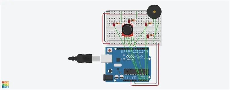
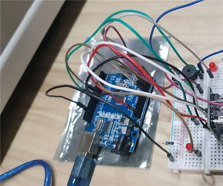
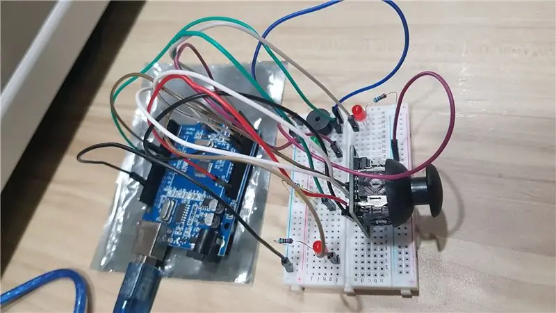
Connectez la carte Arduino Uno au module joystick, en connectant 2 broches d'entrée analogiques aux sorties X Y du joystick.
4 LED à connecter à l'aide de résistances à 4 broches de sortie numérique ou analogique.
Buzzer actif à connecter à une broche de sortie numérique
Étape 2: Code pour la configuration des épingles
int xVal = 0, yVal = 0, butVal = 0, xPin = A0, yPin = A1, joyPin = 13, butPin = 7, speakerPin = 9;
int leftLED = A2, rightLED = A3, topLED = A4, bottomLED = A5;
int sélectionnéLED = 0; // Peut être l'un des A2, A3, A4 ou A5
void setup() {
pinMode(xPin, INPUT);
pinMode(yPin, INPUT);
pinMode (LED gauche, SORTIE);
pinMode (Droite LED, SORTIE);
pinMode(topLED, SORTIE); pinMode(bottomLED, SORTIE);
pinMode(joyPin, SORTIE);
pinMode(buzzerPin, SORTIE);
}
Étape 3: Code pour la détection par joystick
void joystickSenseRoutine()
{
xVal = analogRead(xPin); yVal = analogRead(yPin); butVal = digitalRead(butPin);
joyPin = mapXYtoPin(xVal, yVal, butVal);
analogWrite(selectedLED, 1024);
if (selectedLED != leftLED) { analogWrite(leftLED, 0); } if (selectedLED != rightLED) { analogWrite(rightLED, 0); }
if (selectedLED != topLED) { analogWrite(topLED, 0); }
if (selectedLED != bottomLED) { analogWrite(bottomLED, 0); }
if (joyPin == selectedLED) // Mole Whacked
{
analogWrite(selectedLED, 0);
//
// Ajouter du code pour jouer de la musique/tonalité pour frapper moLED !!
//
}
}
int mapXYtoPin(int xVal, int yVal, int butVal) { if ((xVal < 100) et (yVal 400)) { return bottomLED; }
else if ((xVal > 900) et (yVal 400)) { return topLED; }
else if ((xVal 400) et (yVal < 100)) { return leftLED; }
else if ((xVal 400) et (yVal > 900)) { return rightLED; }
else { return -1; }
}
Étape 4: Code de routine de la boucle principale
boucle vide() {
pour (int i = 0; i < longueur; i++)
{
if (random(0, 100) > 90) { selectedLED = anaPinMap(random(2, 6));}
// Ajoutez le code pour la musique du jeu ici
// *** *** ***
//
}
int anaPinMap(int randNum) {
if (randNum == 2) { return A2; }
else if (randNum == 3) { return A3; }
else if (randNum == 4) { return A4; }
else if (randNum == 5) { return A5; }
}
Étape 5: Prêt à essayer

Étape 6: Implémentation Arduino Nano pour le prototype
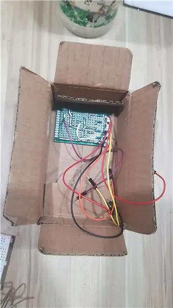
Même implémentation réalisée avec Arduino nano dans la maquette, carte sur mesure avec LED, résistances et buzzer, et commutateur de joystick X-Y.
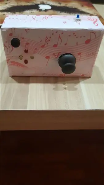
Étape 7: Prototype Whack-a-MoLED emballé final pour présenter votre bien-aimé
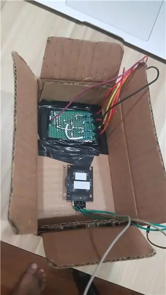
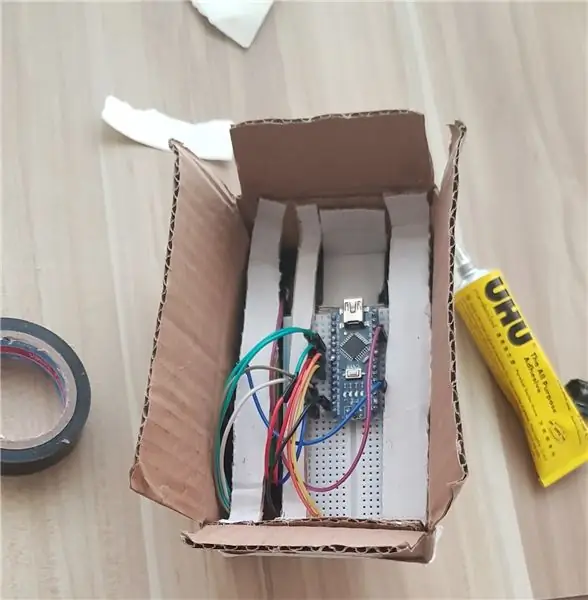
Fournitures pour prototype:
Boîte en carton simple (Minimum 4cmX6cmX3cm), pièces de carton supplémentaires pour le support.
Papier décoratif pour recouvrir le châssis (facultatif)
Adhésif/colle polyvalent
Mini planche à pain (facultatif)
Arduino nano
Petit PCB universel
Batterie 9V pour alimenter Arduino nano (connecter à la broche Vin).
Commutateur SPDT
Reste des alimentations (LED, résistances, joystick, buzzer, fils) comme décrit à l'étape 1 ci-dessus.
Conseillé:
Comment fabriquer une antenne double biquade 4G LTE en quelques étapes faciles : 3 étapes

Comment créer une antenne double biquade 4G LTE Étapes faciles : La plupart du temps, je n'ai pas une bonne force de signal pour mes travaux quotidiens. Donc. Je recherche et essaye différents types d'antenne mais ne fonctionne pas. Après une perte de temps, j'ai trouvé une antenne que j'espère fabriquer et tester, car ce n'est pas un principe de construction
LED Whack-a-mole: 5 étapes
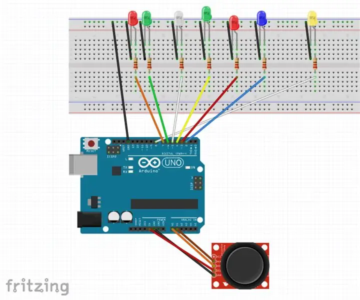
LED Whack-a-mole : Ce jeu de "Whack-a-mole" utilise sept LED et un joystick. Il y a 4 "taupes" sur ma carte, représenté à partir de la gauche par les 3e, 4e, 5e et 6e LED. L'une de ces quatre LED s'allumera de manière aléatoire et offrira une lumière fixe
Whack a Button Multijoueur : 4 étapes
Whack a Button Multiplayer : Un jeu comme un Whack-a-Mole. Utilisant des LED et des boutons. Il existe 2 modes : 1 secondeLEVEL_3 : 2 diodes pendant 0.7 secondesEt pour le multip
Whack-a-Mole! (Pas de code !): 9 étapes (avec photos)
Whack-a-Mole! (Pas de code !) : Bonjour tout le monde ! Je suis revenu de l'abîme de non-publication et je recommence avec un autre Instructable ! Aujourd'hui, je vais vous expliquer comment, en utilisant les seuls fondamentaux de la circuiterie, SANS AUCUN CODE, pour construire Whack-a-Mole ! Vous obtenez 30 secondes
Whack-a-somebody: 6 étapes (avec photos)
Whack-a-somebody : Ce projet était pour « Creative Electronics », un module de 4e année d'ingénierie électronique de Beng à l'Université de Malaga, École des télécommunications (www.etsit.uma.es). Dans ce instructable, nous avons créé une version personnalisée du Whack-a-mole
